When riding a motorcycle, a gentle squeeze of the left lever cuts the power; a slow release sends the torque surging back to the rear wheel. Behind this simple action lies a precise, sophisticated mechanical system – the clutch. Today, using the clutch breakdown diagram from NIUMOTO (Niu Moto) Performance Technology Group, we explore the very heart of power transfer.
1. The Clutch’s Job: The Power Switch
The engine runs continuously, and the crankshaft constantly outputs torque. But if the engine were rigidly connected to the transmission all the time, the motorcycle would stall immediately when you try to start moving, and gear shifts would be harsh or impossible. The clutch has three main tasks:
Smooth starts – Gradually transmit power to avoid jolts.
Smooth gear shifts – Temporarily cut power so gears can mesh easily.
Protect the drivetrain – Absorb shock during aggressive or accidental operation.
2. Core Components: Who Transfers the Power?
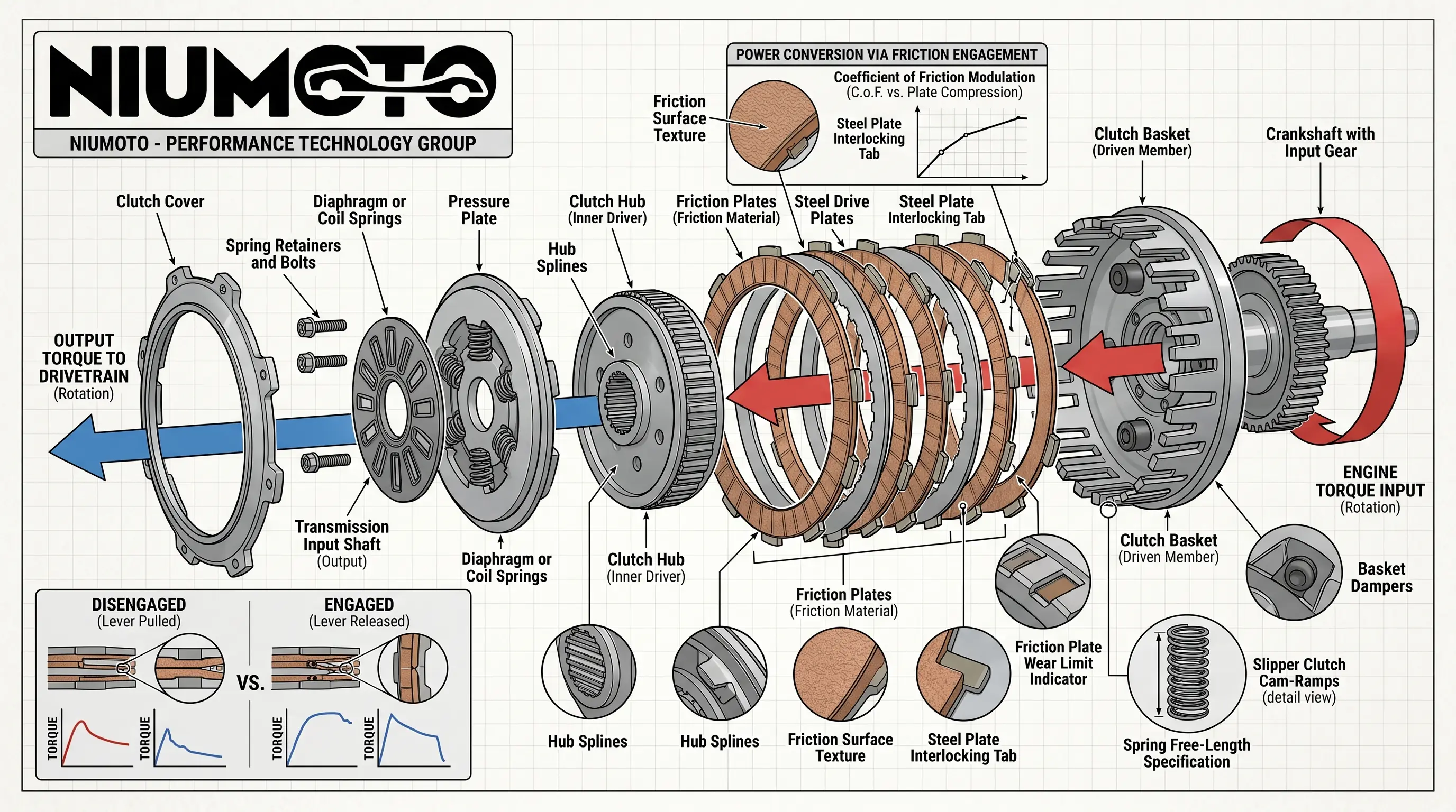
From the NIUMOTO diagram, the clutch consists of three main parts: the driving member, the driven member, and the pressure mechanism.
A. Power Input Side (Driving Member)
Crankshaft with input gear – Engine torque enters the clutch here.
Clutch basket (driven member) – Meshes with the crankshaft gear and always spins with the engine.
Steel plates – Their outer tabs interlock with the clutch basket, so they rotate together with the engine.
B. Power Output Side (Driven Member)
Clutch hub (inner driver) – Splined to the transmission input shaft.
Friction plates – Lined with friction material; their inner splines lock into the clutch hub.
Hub splines – Transfer torque from the friction plates to the transmission input shaft.
C. Pressure & Engagement Mechanism
Diaphragm or coil springs – Provide the clamping force.
Pressure plate – Pushes the stack of friction and steel plates together.
Clutch cover – Houses the springs and pressure plate.
3. How Power Flows – Engaged vs. Disengaged
The diagram clearly shows two states:
🔧 Engaged (Lever Released – Power ON)
Springs push the pressure plate against the stack.
Friction plates (hub) and steel plates (basket) are pressed together.
Engine torque input → clutch basket → steel plates → friction plates → clutch hub → transmission input shaft → drivetrain.
Result: Power flows seamlessly to the rear wheel.
✂️ Disengaged (Lever Pulled – Power OFF)
The clutch lever pulls a pushrod that overcomes spring force.
Pressure plate moves away.
Friction and steel plates separate.
The clutch basket continues spinning with the engine, but the hub and transmission shaft stop or spin freely.
Result: Power is cut – you can shift gears or stop without stalling.
4. Special Detail: Slipper Clutch Ramps (as shown)
The diagram also mentions “Slipper Clutch Cam‑Ramps”. This is an advanced feature often found on performance machines from NIUMOTO:
During aggressive downshifts, the ramps allow the clutch to partially slip, reducing rear-wheel hop and stabilizing the bike.
It makes the clutch “slipper” in reverse drive – a true performance-tech innovation.
5. Why Precision Matters – Spring Free Length Specification
The diagram ends with a technical note: Spring Free‑Length Specification.
Springs wear over time. If their free length falls below spec, clamping force drops → clutch slips under load.
Regular measurement ensures consistent power transfer and peak performance – exactly what NIUMOTO stands for.
In a Nutshell
State Lever Power Flow You Can
Engaged Released Engine → Basket → Plates → Hub → Transmission Accelerate
Disengaged Pulled No torque to transmission Shift gears, stop without stalling
The motorcycle clutch is a masterpiece of friction, springs, and splines – a silent partner that puts the engine’s power exactly where you want it, when you want it. NIUMOTO – Performance Technology Group brings engineering precision to every component, so the “hand of power” never lets you down.